|
Micro Power Digital Ignition System
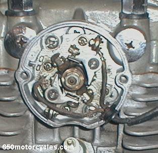
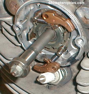
Stock ignition breaker points above on
the left hand side of the motor. Left and right sides are
designated as such when sitting on a motorcycle facing forward in
the riding position. This is a 1975 model XS 650. This ignition
fits all years.
Two mounting screws are removed and the
old points plate is removed exposing the points cam.
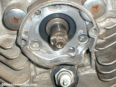
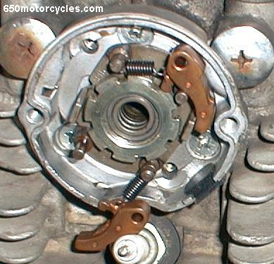
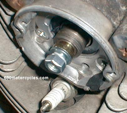
The 10 mm nut and lockwasher are removed
and the points cam comes off the governor rod and then the rod
through the center of the camshaft slides out the other (right)
side.
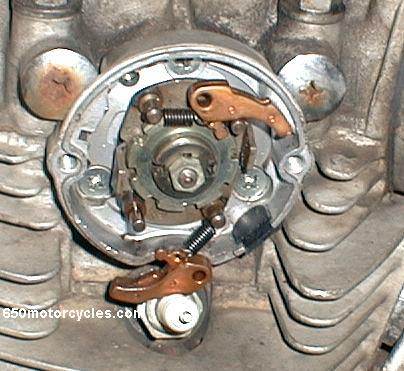
Remove two small "C" clips
and the mechanical advance governor flyweights are removed from
the pivot pins.
The governor rod is slid out of the
camshaft and not used with the new ignition system.
Use a punch to loosen the ring nut that
holds the advance unit in place.
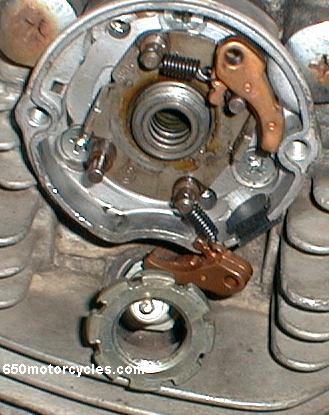
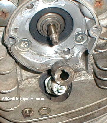
The advance unit will come off a little
at a time as the ring nut is removed. (counter clockwise /
anti-clockwise).
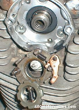
The above items are removed and only a
stepped bushing with a nut and washers will be installed on this
side.
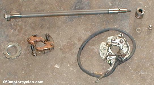
Stock troublesome governor rod, advance
unit and points plate are all removed permanently.
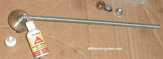
The new ignition "hall effect"
magnet trigger is secured with stud and bearing locktite on one
end of the 8mm threaded rod provided.
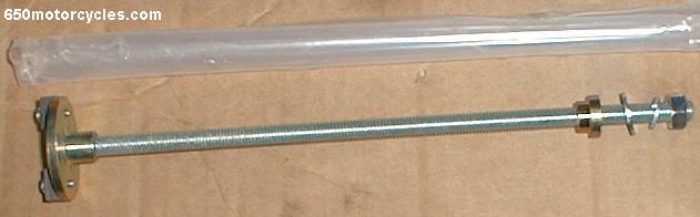
This simple rod mounts the ignition
trigger magnet assembly centered solidly through the camshaft
with the machined shoulder on the left above, and the stepped
bushing on the right fitting the original camshaft bore. .
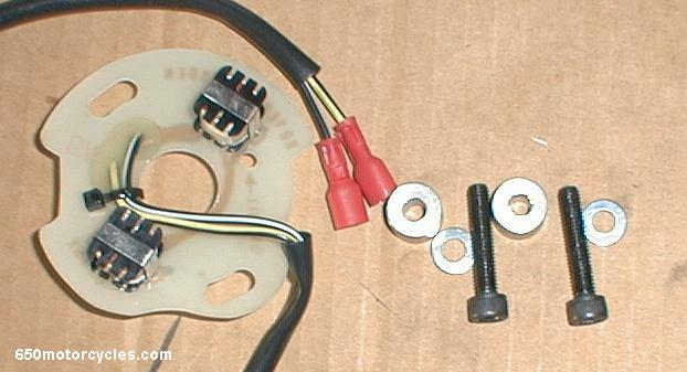
Magnetic pickup mounting plate bolts
right in where the old points plate was.
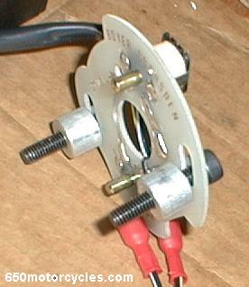
Steel washers provided go under the heads
of the allen bolts (shcs) provided and the two machined aluminum
spacers go behind the plate to hold it in the proper mounting
position.
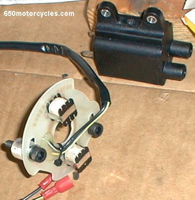
Small metal dowels provided in the
mounting holes for the coil save damage to the plastic coil
mounting flange.
Coil with steel mounting spacers on the
left, aluminum mounting spacers shown where they go on the rear
of the timing plate center, magnet trigger shown installed with
red locktite on the 8mm mounting rod at the top right.
Magnetic trigger in its installed
position in the camshaft left end.
Stepped bushing, flat washer, lock
washer, and the nut that secure the rod are all that goes on the
right side end.
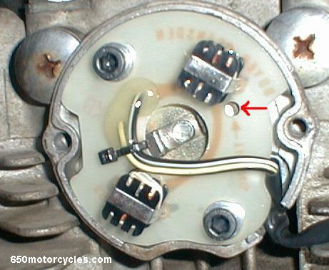
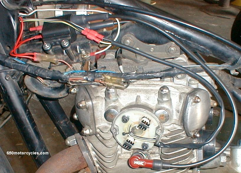
With the crank position set at the total
lead position (shown below) the timing magnets are set with the
white dot of paint on either magnet visable centered in the
timing setting hole provided in the sensor plate at the red arrow
above.
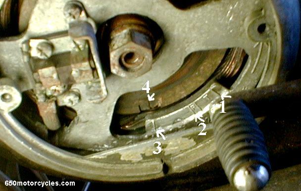
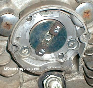
The mark at number 4 above is the TDC
(top dead center) timing mark that is in the center of a small
square recess in the stator that is bolted and keyed to the left
end of the crankshaft. Set that rotor TDC mark (#4) to line up
with the line at # 3 above. Number 3 is the total lead mark where
the timing is set. All you do is turn the crank with a 17mm
socket to line up #3 and #4 above, and set the white dot on
either magnet in the previous image above this one at the red
arrow in the timing index hole and that's it. You can check the
timing with a timing light later if you like, or advance or
retard it to your liking. Number 2 was used for setting the
points, and number 1 indicates when the pistons are at top dead
center.
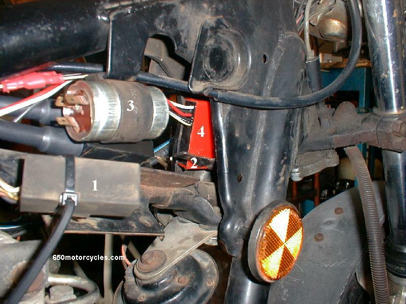
I moved the rubber coated control box #1
(above) from the center of the forward frame cavity, it slid on
bracket #2. I tie wrapped it with wire ties to the unused right
hand coil bracket. Then I bent down the forward bracket #2 to
allow the digital control box to be located in that empty forward
space. (see below also) The flasher #3, I simply turned around
the rubber mounting bracket to offset it to the right side and
allow room to mount the new coil on the old left hand coil
mounting bracket.
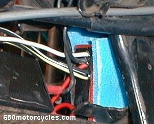
I sandwiched the solid state control
box in some foam padding in its final position behind the
steering head.
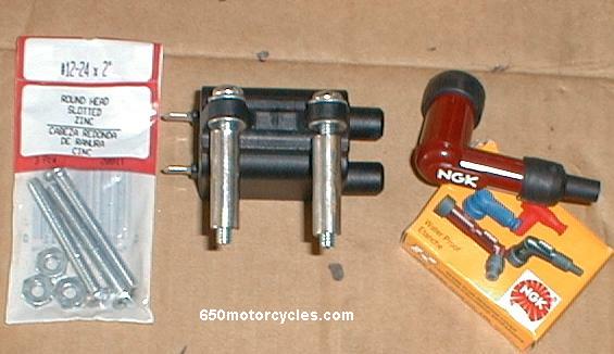
I made two coil mounting spacers from
some 3/8" OD stainless tubing that are 1.250" long. Any
type of plumping pipe or spacers could be used. 12-24 screws fit
through the supplied small coil mounting flange dowels perfectly.
Washers are on each side are to prevent crushing the plastic
flange and they fit against the metal dowel inserts that come in
the coil.
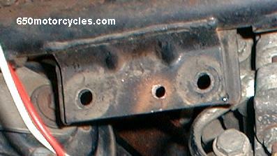
Stock left hand coil mounting bracket
gets one 1/4" hole drilled in it. I mounted the new coil on
the front two holes above, and used the old rear mounting hole
for a chassis/engine ground.
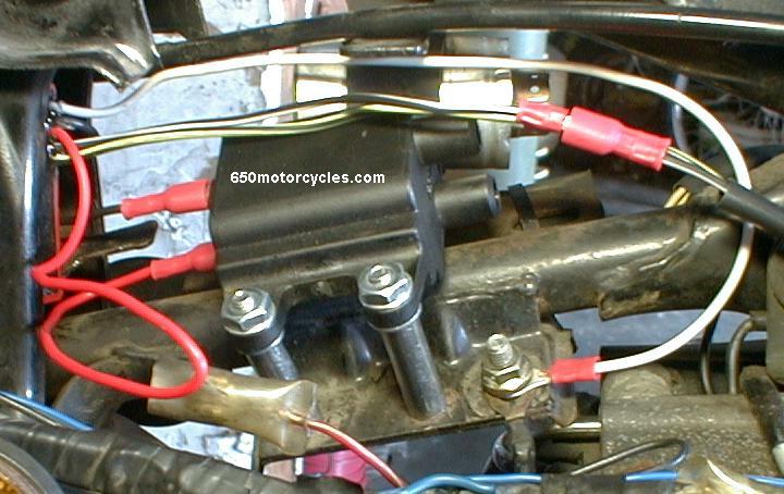
Coil mounting bolts are tightened with
red locktite on the screws. I ran the red wire from the digital
control box with the spade connector already crimped on it to the
+ terminal marked on the coil, then cut it in the center at the
fold above to bring switched voltage through the stock power
supply red wire with the white tracer from the stock female
double bullet connector. (see below image)
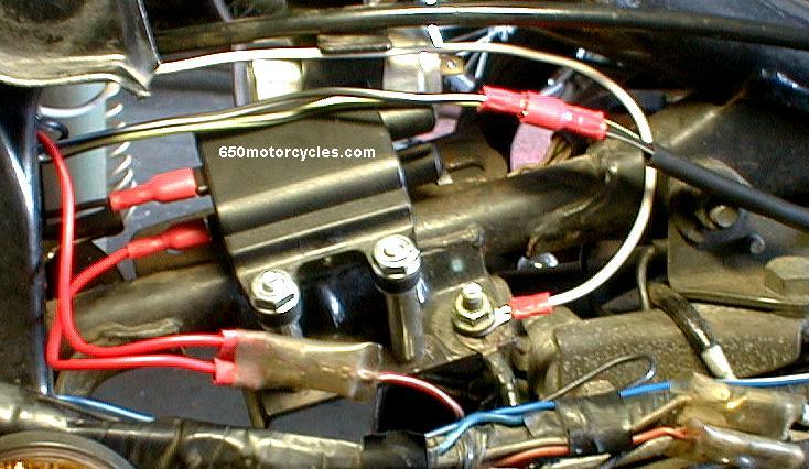
I installed the 2 male bullet connectors
provided with the kit and plugged them right into the stock
harness power connector to the old coils above. Now switched
voltage goes to the coil, and to the digital control box. The
black wire from the control box plugs right on the negative coil
connection. The white wire from the control box I ran to ground
(earth) and bolted it in the old unused stock coil mounting hole
above. The only other connections are the pair of wires at the
top above, (black with a white tracer, and black with a yellow
tracer) they simply plug into the pair coming from the magnet
trigger sensor plate. That's all the connections except for the
high tension spark plug wires! (below)
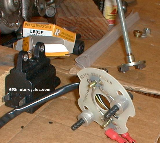
I soldered on the special high tension
wire coil terminal connectors.
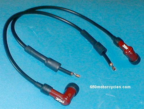
The spark plug wire length provided I cut
exactly in half, and those lengths worked fine for both
cylinders. The new NGK resistor plug caps (also provided) have a
self tapping screw in the end that you screw right in to the
spark plug wire.
Everything is shown in this one image,
all the wire connections and where they go, except the spark plug
wire on the right side!
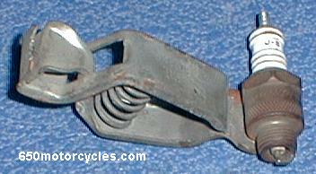
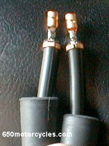
This tester I made long ago by soldering
a spark plug on a clip, that is clamped on the connector end of a
spark plug, and the plug wire is installed on to it. Both plugs
will fire while the engine is running. (below)
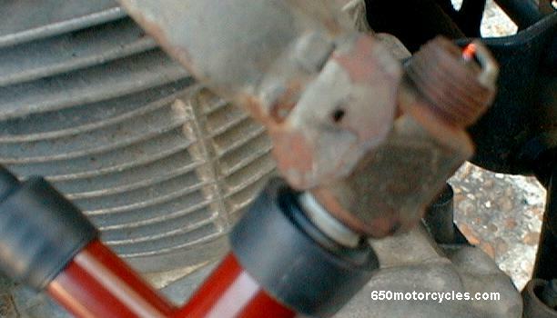
The ignition system improves starts, idle
and revs through the rpm range perfectly. It has a big fat spark,
shown above while the engine is running! The ignition is firing
the engine spark plug and the tester spark plug at the same time
on the right hand side!
|